|
|||||||||||
 25.03.2021., 13:16
|
#1 |
|
Moderator
Datum registracije: Sep 2006
Lokacija: St
Postovi: 22,554
|
Dell Optiplex 7010/9010 Front I/O panel pinout
Ove serije se mogu nabaviti relativno povoljno a ako netko želi prebacivati u neko drugo kućište onda nastaju problemi. Radi se o tome da je Dell (osim ATX24) koristio custom konektore / pinout za Front I/O panel i power switch. Jedno od rješenja je preseliti origigi Front I/O panel i power switch skupa sa kabelima, a drugi je (snađi se druže) DIY varijanta. Srećom ekipa je sve opisala i dokumentirala: This thread describes the issues with installing an Optiplex 7010/9010 motherboard into a 3rd party ATX case. There is another thread for the Optiplex 7010 power switch and power LED pinout. Optiplex 7010 power switch I have observed if the front I/O cable is detached from the motherboard, there is an 'Alert! Front I/O Cable failure.' error message when booting up the PC. The F1 key must be pressed to continue. I thought I would investigate what causes this and other 'Alert!' messages. The Optiplex 7010 and 9010 (I have both) appear to use virtually the same motherboard in the mini tower (MT) variant. The key difference is 9010 has BIOS support RAID. The Precision T1650 looks very similar and also supports ECC RAM - it is also offered with Xeon e3-1200v2 family of processors, the fastest being the i3-1290v2. The fastest Dell certified processor for the 7010/9010 is the i7-3770. However, the e3-1230 v2 Xeon processor is apparently known to work in the 7010 too according to one Youtube video posted back in 2015. The Front I/O socket on the motherboard is smaller than normal. It appears the pins have a 2mm pitch instead of the typical 0.1" (2.54mm) pitch too. Update (30 Oct 2018): I've since discovered a post on reddit created by 'BlastingKap' two months earlier, who had also examined the Front I/O pinout on an Optiplex 7010: https://www.reddit.com/r/buildapc/co...transplanting/ Update (28 Apr 2019): I also came across this youtube video https://youtu.be/Bz6s4wB-MDM 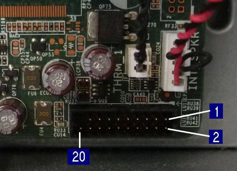  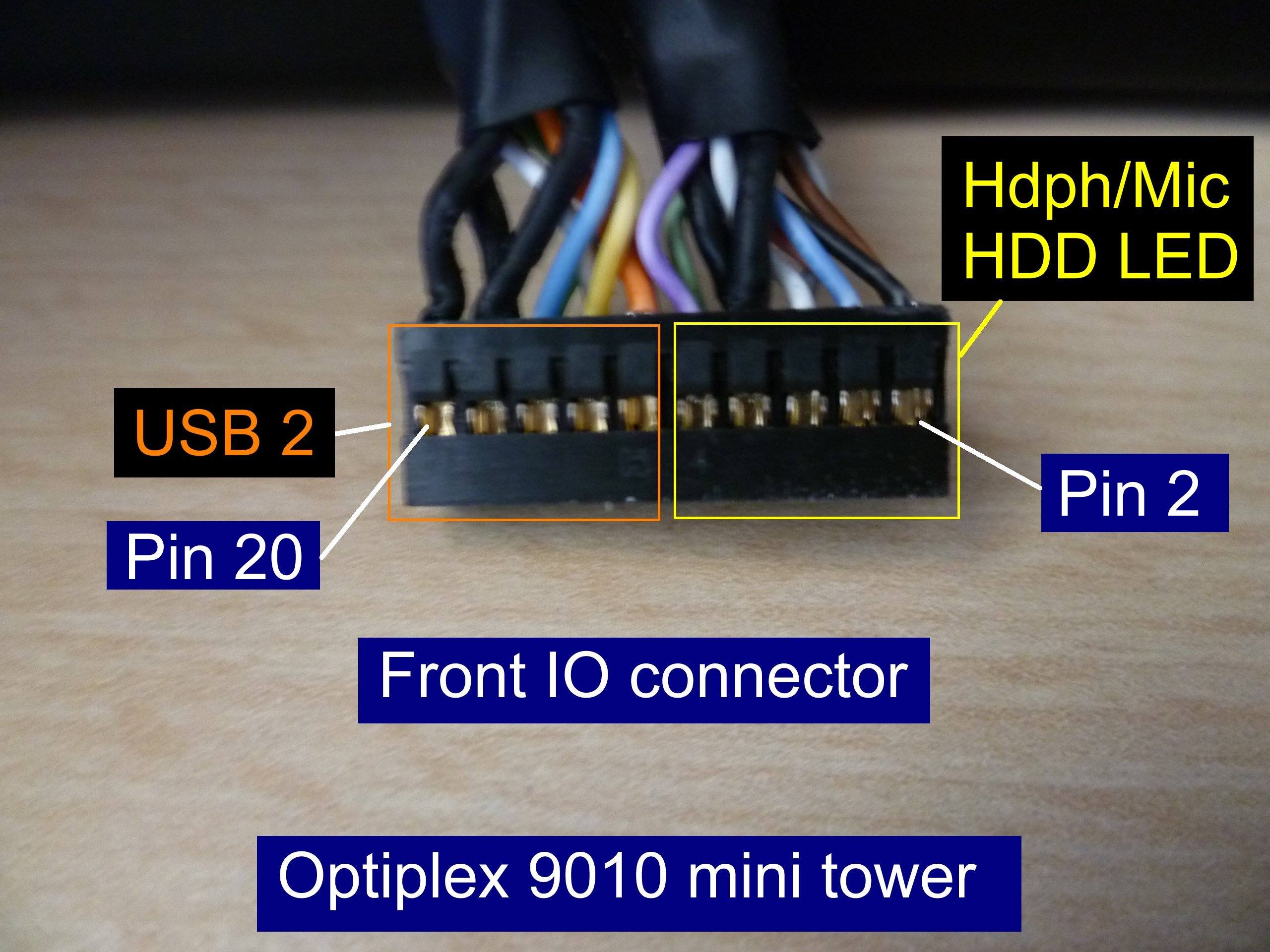 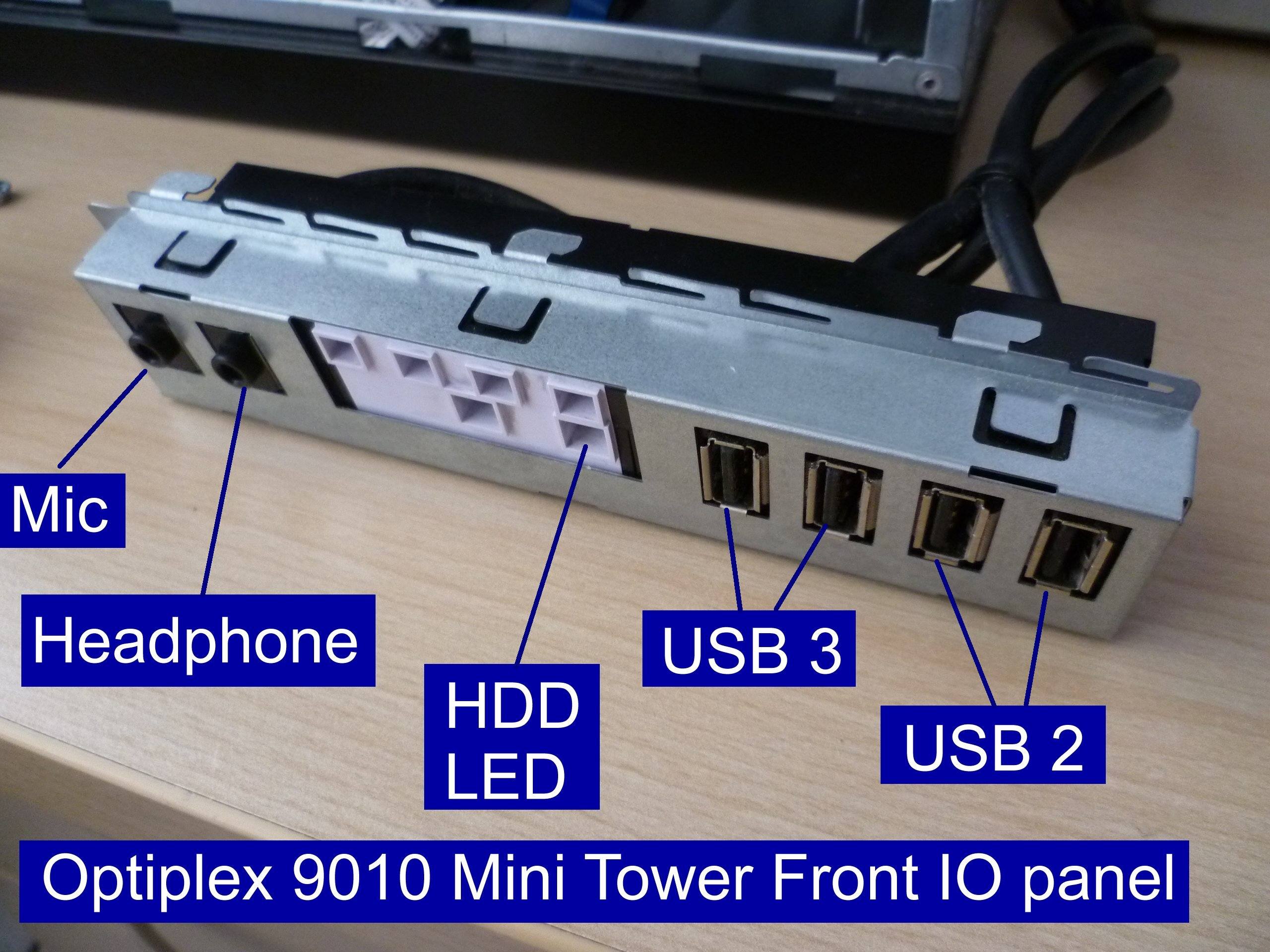 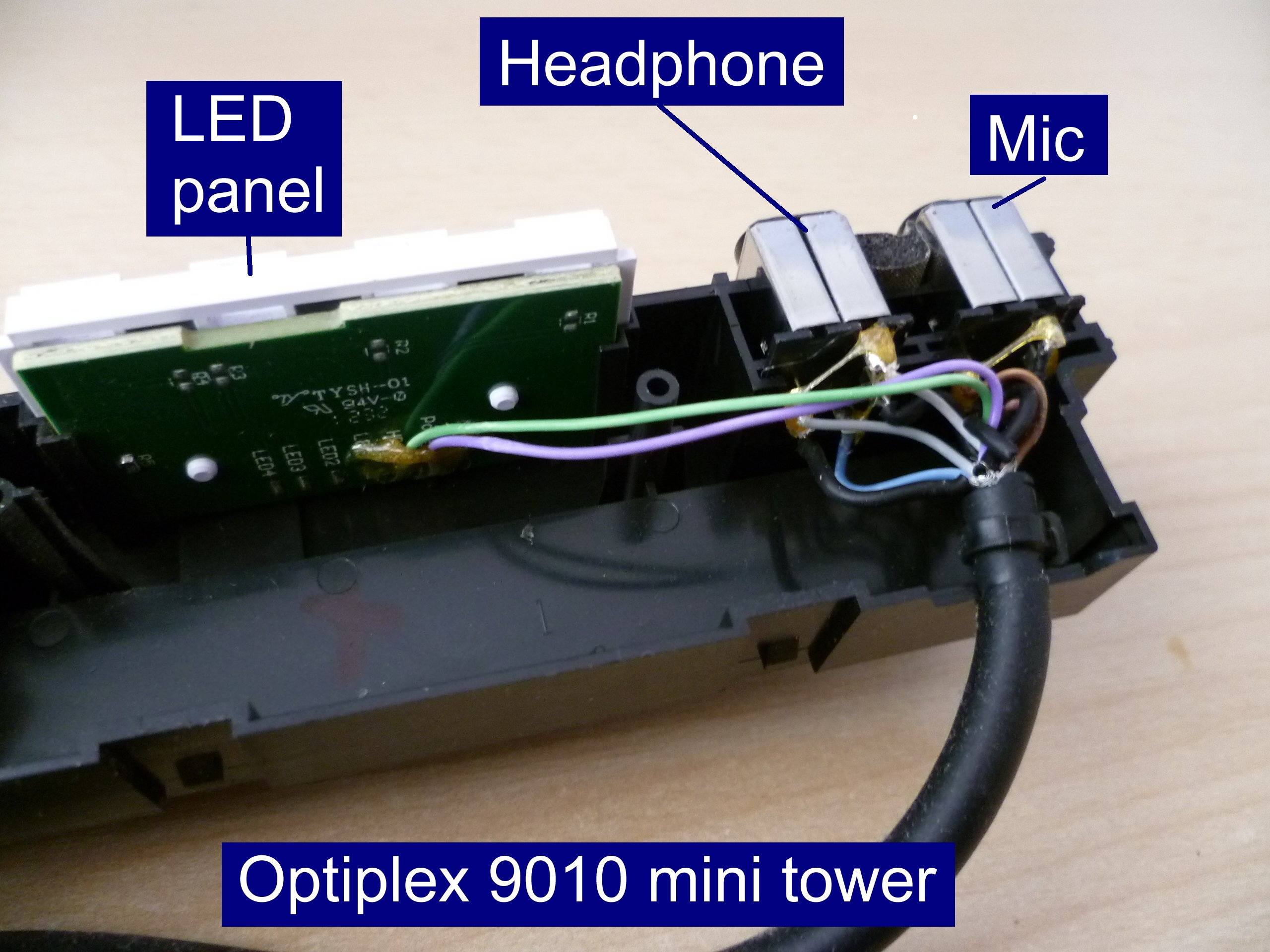 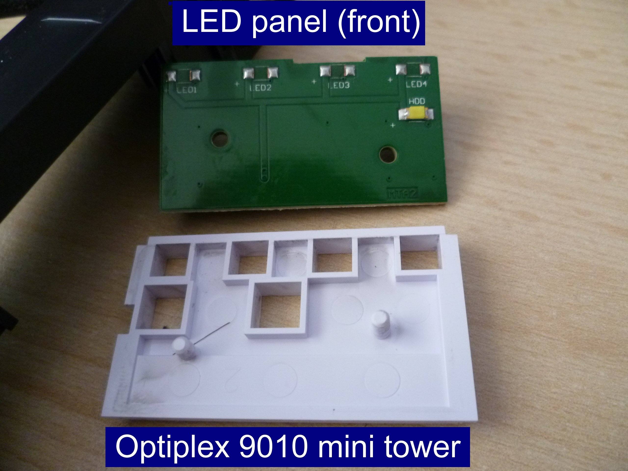 Note the presence of a 1k resistor to limit the current through the LED. 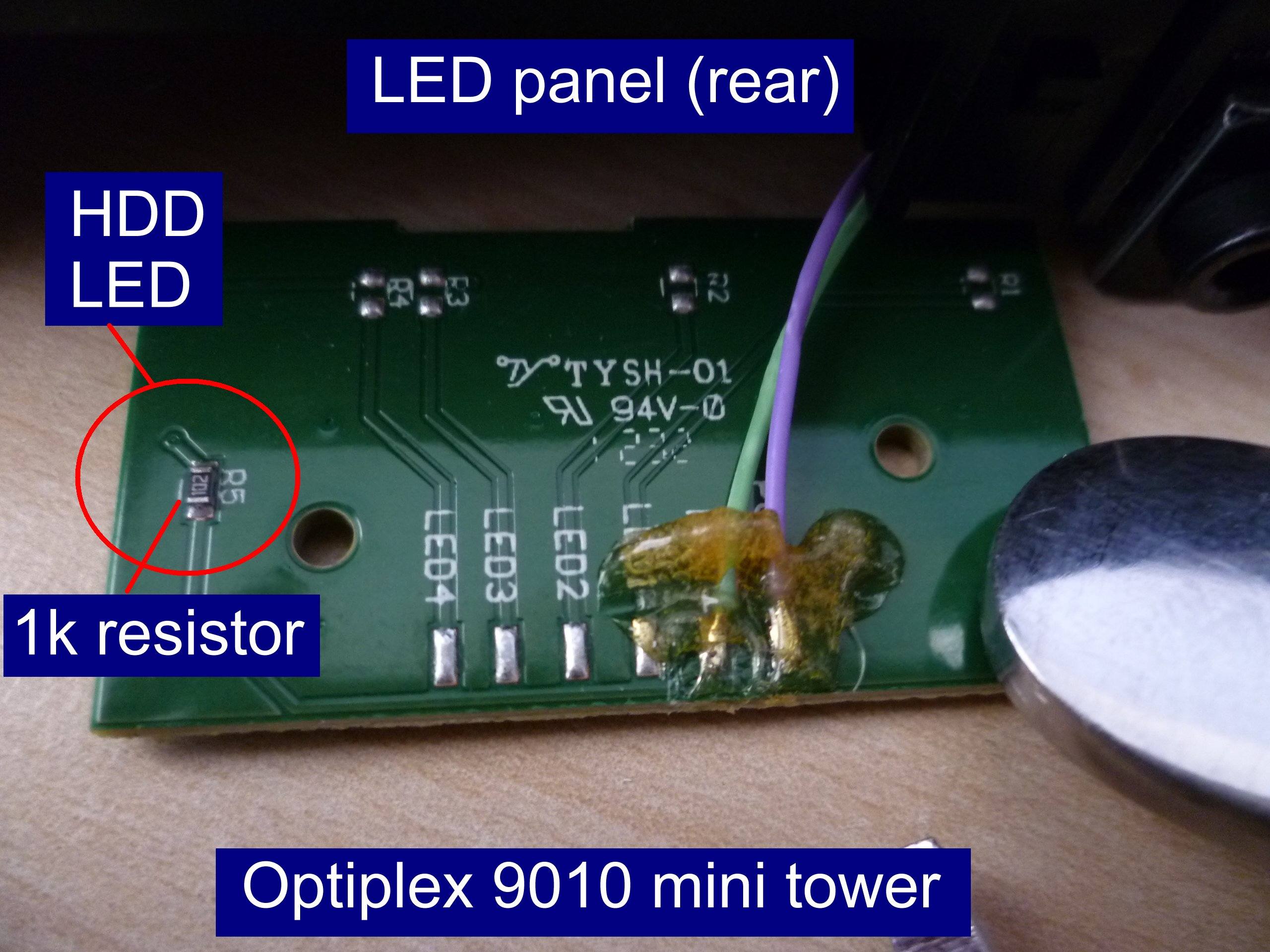 The front USB3 sockets are served by a separate cable which plugs into blue coloured USB header socket on the motherboard. 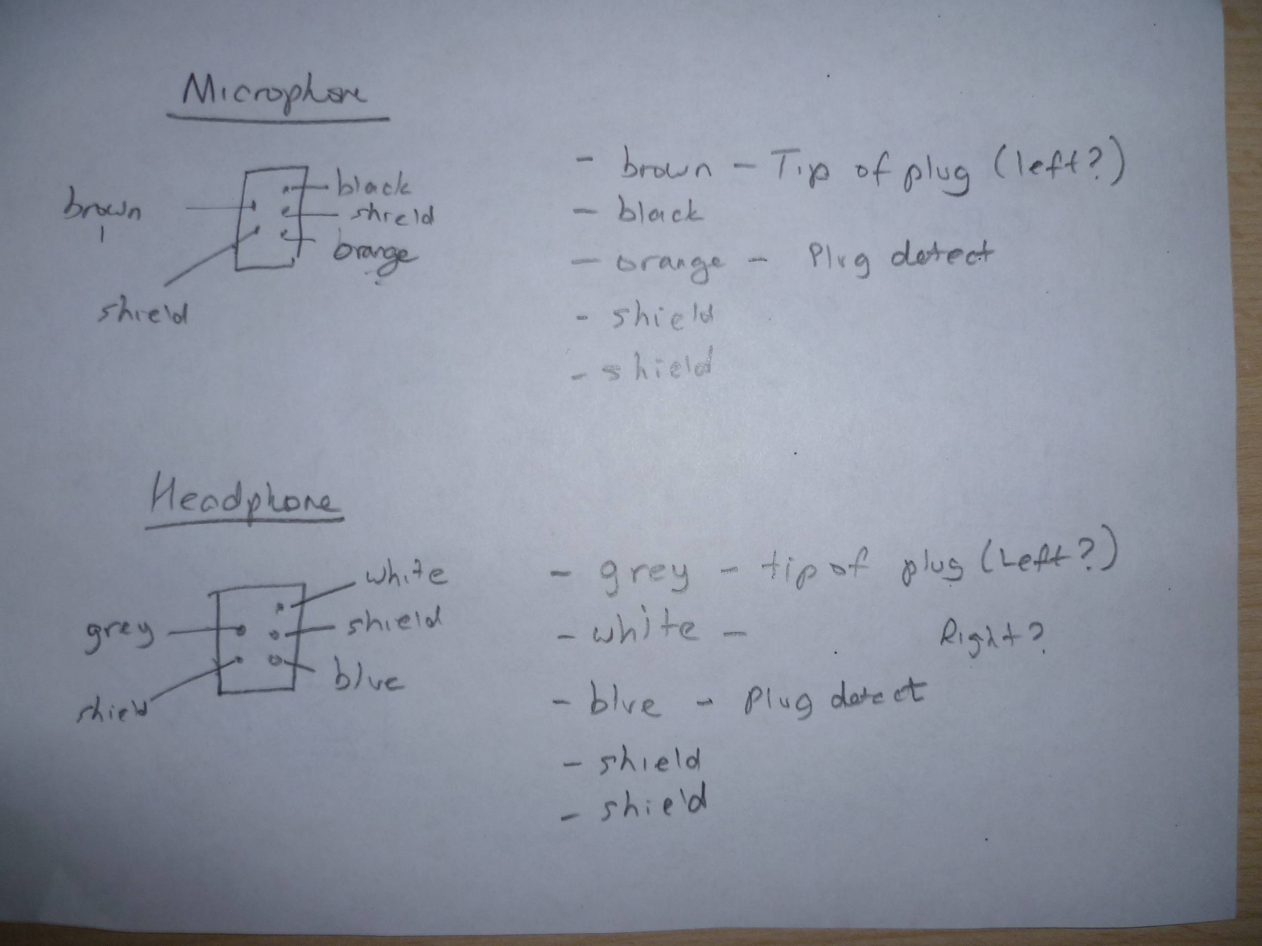 The pinout for the microphone and heaphone have a non-standard layout. The HDD LED requires an extra 1k resistor. The USB2 pinout seems to have a standard layout but a normal 0.1" pitch USB2 header plug won't fit onto the 2mm pitch pins.  It wouldn't surprise me if the Optiplex 7020/9020 and Precision T1700 uses the same pinout for the Front I/O connector. The key features of the 7020/9020/T1700 are the use of Intel 4th gen Haswell processors. The MT/DT motherboards have an 8 pin power connector, and a 24 pin ATX to 8 pin adapter is required when planning to use a third party ATX PSU. The Optiplex 7010/9010 runs Windows 10 just fine. I have encountered some USB3 and HDMI issues. Fortunately, there are some fixes for them. The 7010/9010 can run macOS High Sierra or Mojave when using a processor with Intel HD4000 graphics, otherwise specific graphics card such as a low cost GT710 is required for any other processor. A mac/macbook is required to create the USB bootable installation media for macOS. https://www.tonymacx86.com/threads/g...ion-ii.251736/ Izvor > https://linustechtips.com/topic/9877...-panel-pinout/ Isto tako "vezana tema" sa informacijom za power switch: The OEM cable has a LED in the center of it connected to the orange and light blue cables. I'm trying to figure out which of the cables from the OEM cable do I need to splice with my case cables. 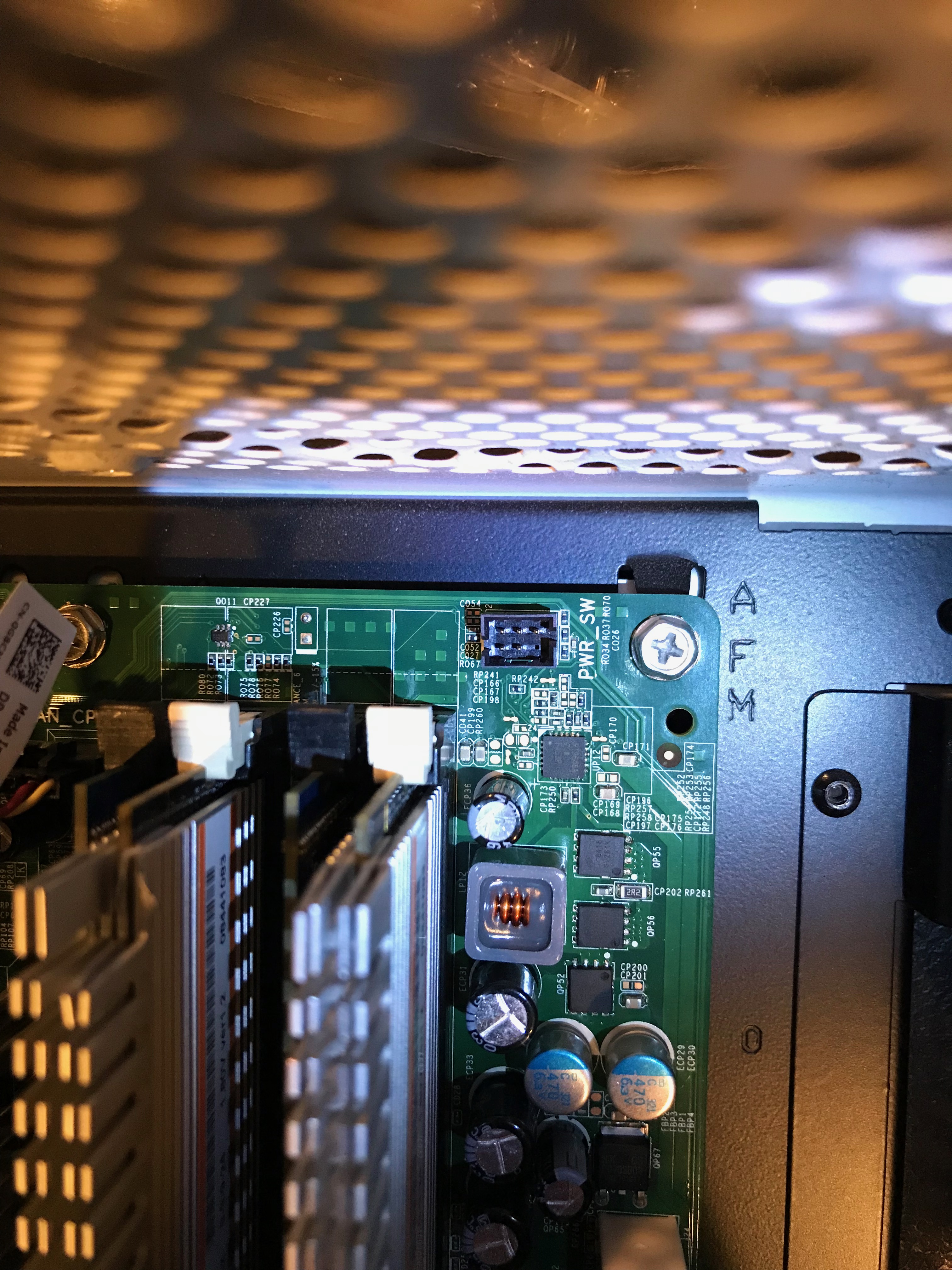 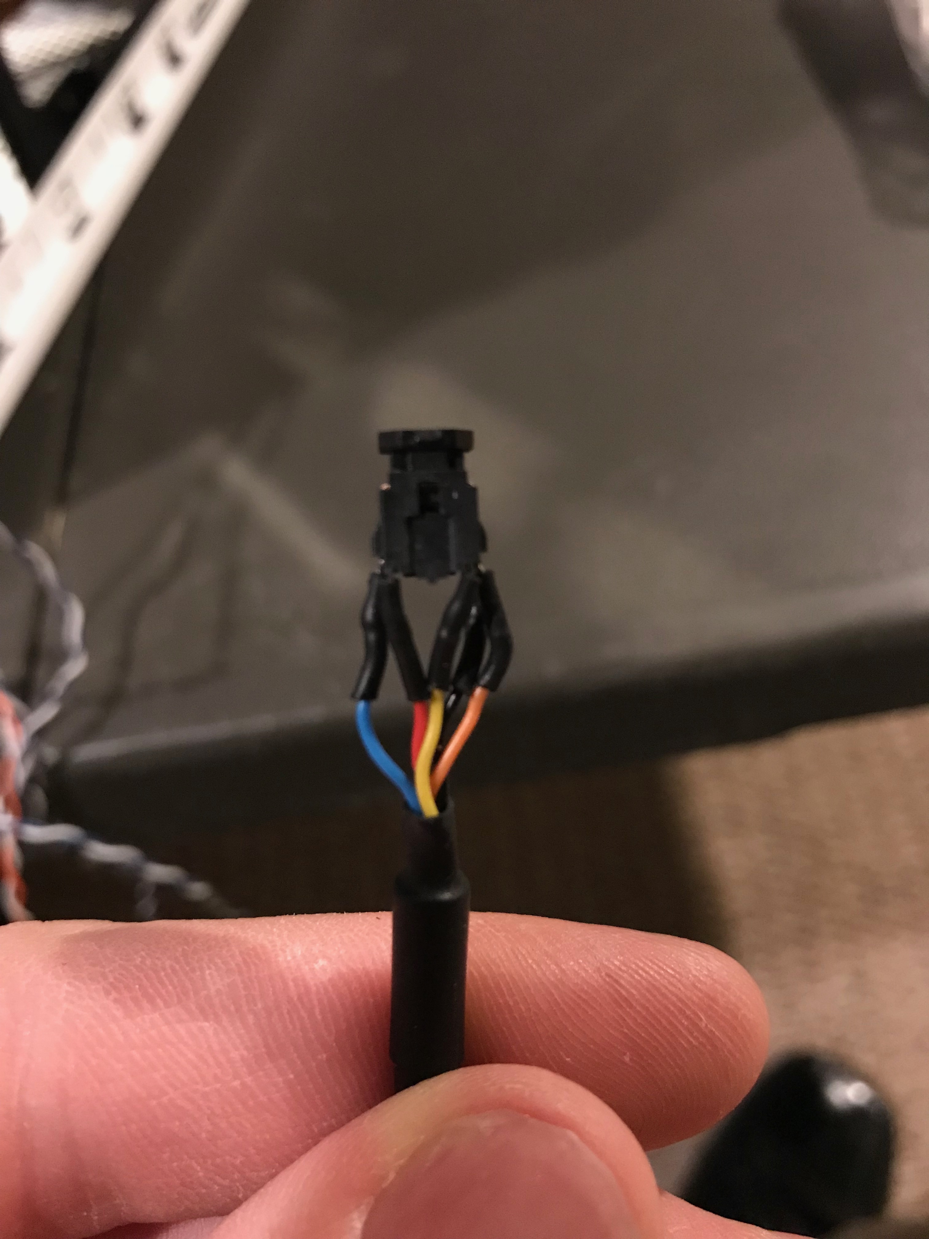 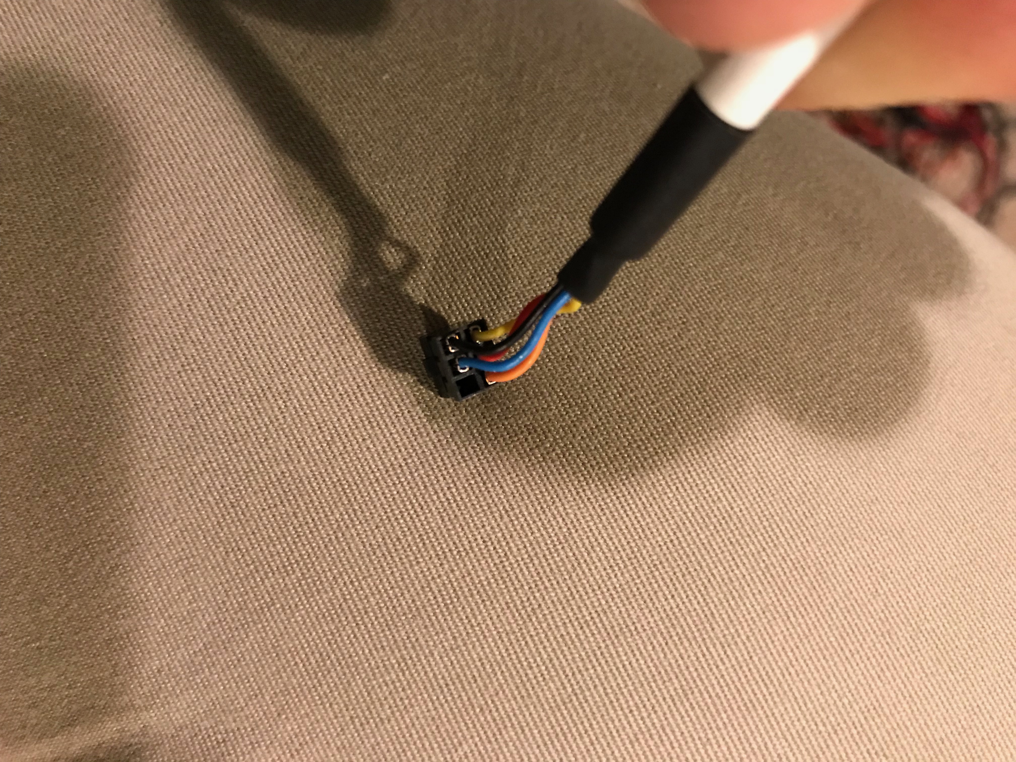  If you are still looking for how to wire up an HDD LED to the Mini tower (MT) and Desktop (DT) motherboards, check out this newer post: Optiplex 7010/9010 Front I/O panel socket pinout Note you may need to add a 1k resistor to prevent overloading the 3rd party case HDD LED. I've also examined the original power switch, and based on info published elsewhere, http://pinoutguide.com/Motherboard/D...1_pinout.shtml Here is how I think the OEM switch and LEDs are wired. Using the original Power switch wiring loom, the Yellow and Black wires are required to turn on the motherboard. To eliminate the 'Alert! Power button failure' message, the Red wire must be connected to Black wire at same time as Yellow wire. The OEM power switch contains a dual colour white/amber LED. 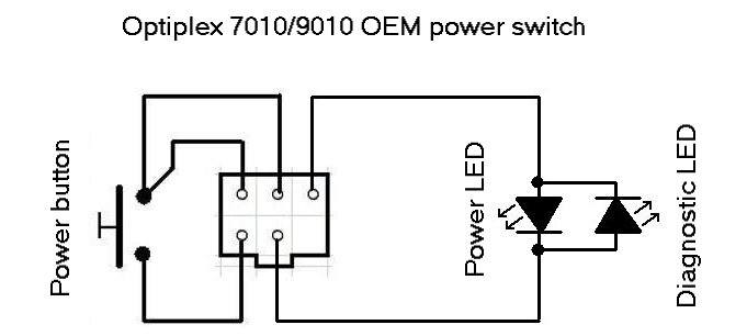 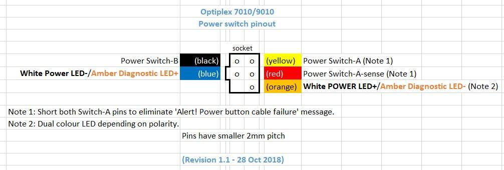 I fabricated some adapters from a redundant 2.5 to 3.5 IDE adapter. The one on the left is for the Front IO panel socket. The one on the right is for the Power switch socket - notice the solder blob (applied to both sides) 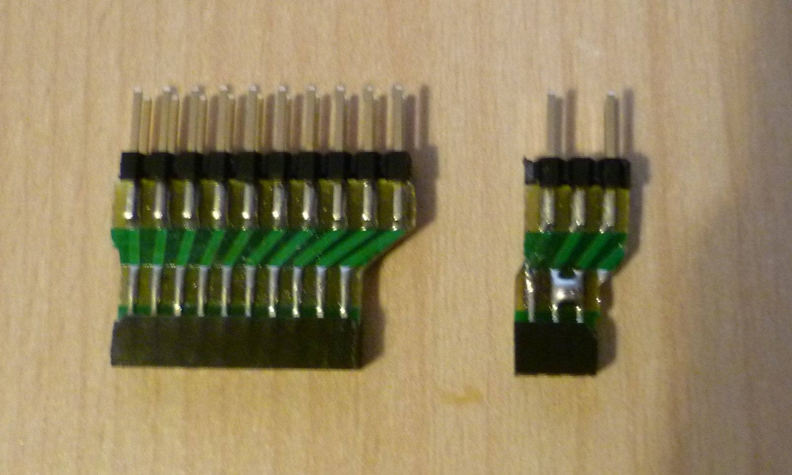 Originally, the power switch adapter had a tendency to lean due to the weight of the Power switch and LED cables. This caused the header plug to lift slightly as confirmed when I am able to straighten and push the adapter back into the socket. Using a P clip to secure the cables seems to have solved the issue for MT/DT motherboards only. Applying some spots of glue to the plug/socket may be another solution. 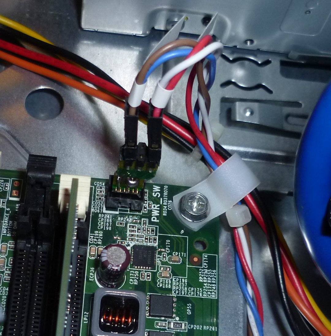 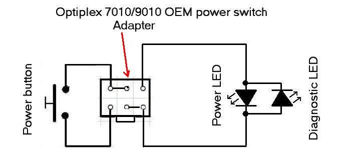 Izvor > https://linustechtips.com/topic/9253...-power-pinout/ Eto, neka se nađe ako bude želio žonglirati sa mobo i kućištem. That's all  |

|

|
|
|
|
|
Oglas
|
Oglasni prostor
|
 |
|
|


